A brief history
O2 (PLMN 234/10) is the largest network operator in the United Kingdom in terms of customers. Including its MVNOs, O2's customer
base totals a whopping 36.2 million customers in a country of just 67 million, meaning they have a market share of 54%.
(Source)
In the past, O2 has had a fairly troublesome history in terms of capacity. Many parts of the UK which used to be more rural have expanded over time, resulting in O2 sites which used to be more than capable of providing decent performance to customers within their zone painful to use. This is extremely prevalent with their main deployments being 800 MHz LTE across rural and suburban United Kingdom.
Capacity management
O2's approaches to capacity management have been successful to varying degrees, but all put together, they result in a positive impact in urban areas, such as large towns and cities. This section won't cover everything, as that's deserving of its own separate page, and Peter already did a great job at it.
This section is heavily influenced by Peter Clarke's O2 capacity management page on his website.
LTE 2300 MHz (B40) and MIMO
O2 holds a total of 40 MHz of unpaired spectrum in the 2300 MHz TDD band (LTE band 40), with the remaining 60 MHz being used by the Ministry of Defence.
O2 B40 LTE sites are often deployed on a 4x4 antenna setup, meaning they can transmit and receive four streams of data simultaneously on 4 separate antennas. Some of O2's Nokia vendor sites also operate an 8x8 antenna setup, meaning that they can transmit and receive 8 streams of data simultaneously (though individual devices are capped at 4 streams).
MIMO is a way of increasing the speed of a data connection by broadcasting multiple signal streams at once. You can learn more about how MIMO works, and why it's beneficial in my previous article.
8T8R 2300 MHz
In a large number of O2's B40 LTE deployments, we've seen them using 8x8 antenna configurations. In 4x4 deployments, sites could transmit four streams of data to two UEs at once, which is referred to as SU-MIMO (single user MIMO). However with 8x8 configurations, sites can transmit four streams of data to two different devices simultaneously, effectively resulting in doubled capacity on that site.
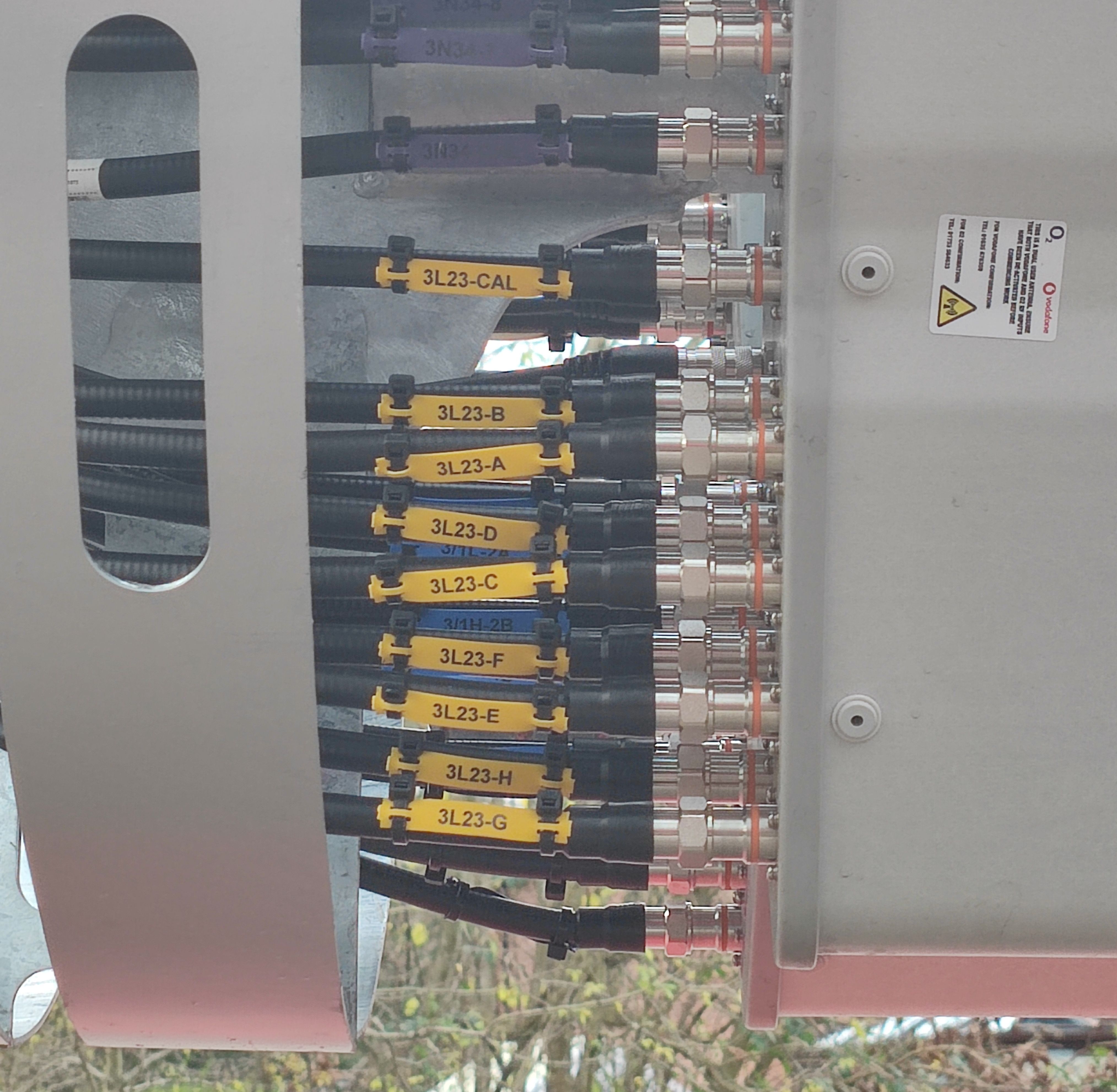
Eight feeders, labelled as 2300 MHz LTE (Band 40) on a brand new O2 Orion monopole deployment.
Massive MIMO
In a few select locations, O2 instead equip their 2300 MHz LTE sites with massive MIMO. This allows for directional beamforming to be used. This is where users data streams are directed towards a user's device, rather than spewed into the air in all directions.
Initially, you might think that this is purely to allow for higher speeds as a result of reduced signal-to-noise ratio and increased power, due to the signal being focused at the UE directly, but there is more to it than this.
In fact, one of the major benefits of massive MIMO is that the site can transmit to multiple UEs at the exact same time. This can be done since the individual streams can be directed such that they do not interfere with one another.
This relies on users being located apart from one another. If two or more users are located near to each other, it is harder for the radio to form beams towards one of them, while keeping a null zone around the other's position.
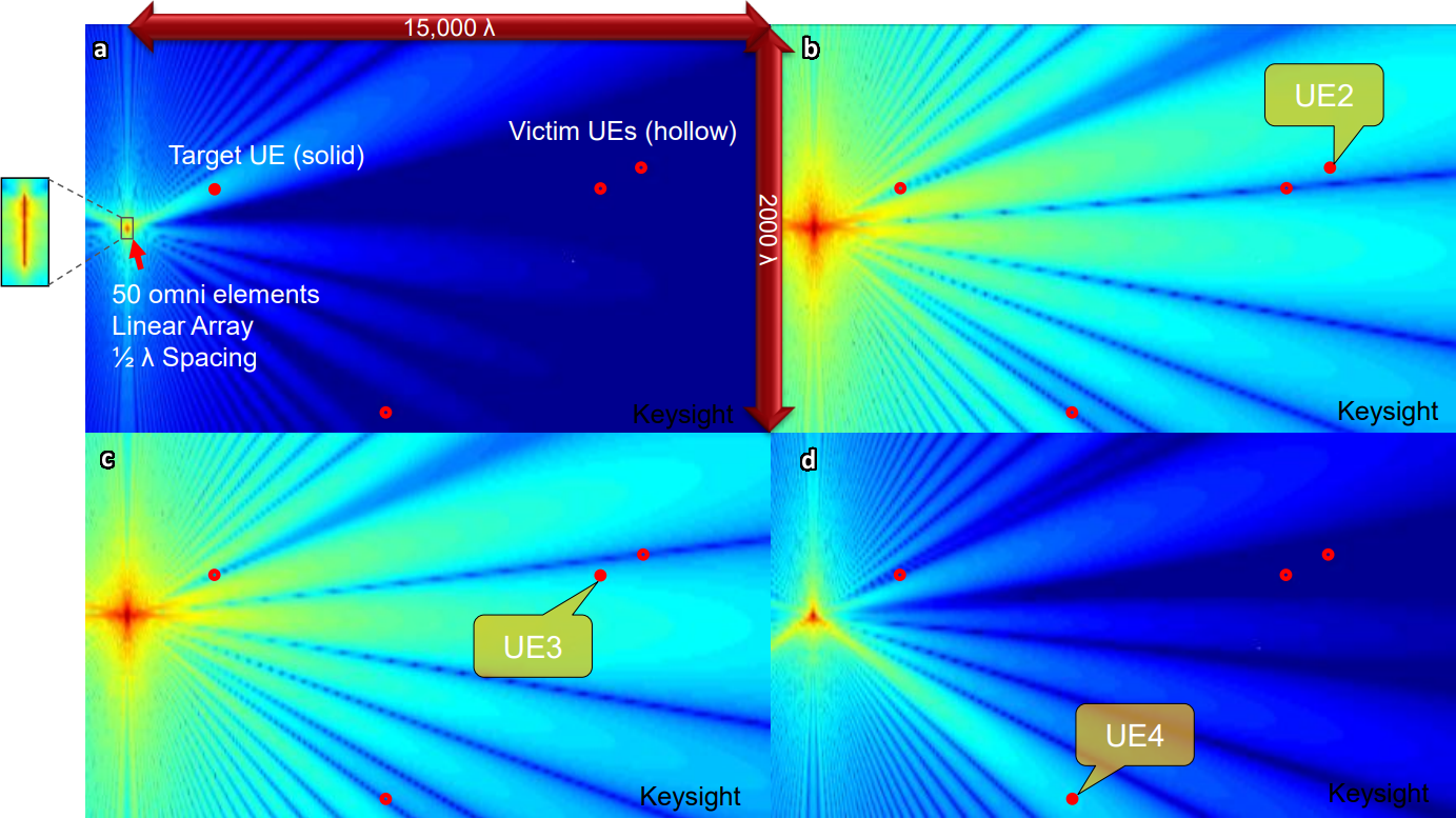
In this diagram, we can see visualisations of four separate beams transmitting to four different UEs. The colour represents signal strength, where red is very strong, and dark blue is very weak. The panels are labelled a, b, c, and d.
It's important to remember that a beam can target a UE specifically, but its radiation pattern means that it also ends up transmitting to other areas too. This can be seen in the first panel, labelled 'a', where the beam is obviously targeting UE1, but signal is detected in other areas away from the UE as well.
While signal is detected in other regions, this is not a real issue, due to the other critical factor in massive MIMO: null zones. Null zones are areas of weak or no signal. The antenna ensures that all other UEs other than the target are in 'null zones'. In all four panels, you can see that the target UE has strong signal, while all other UEs are located in null zones.
These null zones prevent UEs from hearing two conflicting and interfering streams, which would cause an error and require the data to be retransmitted, reducing overall throughput capability.
Image credit: Keysight Technologies, keysight.com